| 上一篇 | 目录 | 下一篇 |
闪存日志存储在飞控上的数据闪存器(或者TF卡中)中,飞行后可下载。默认情况下,它们第一次配置飞控时候创建的。以下介绍如何配置和访问闪存日志。
注意:
遥测日志(也称为“tlogs”)收集与闪存日志类似的信息(更多信息请参见使用日志诊断问题)。
如果你的飞控生成闪存日志时出现错误-包括常见“IO 错误”,请尝试换SD卡。你也可以选择使用专用工具(例如H2testw)来测试下SD是否正常。一般情况下,飞控板电压低也导致记录出问题。
日志记录参数
一些常用的参数有:
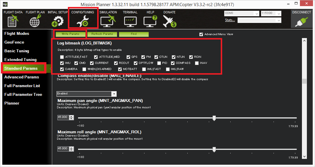
LOG_BITMASK:记录项目的位掩码。一般情况下使用默认值,或设置为“0”禁用日志记录。
LOG_DISARMED:设置为1将在通电时开始记录,而不是在飞行器在解锁时候启动,这样对于解锁前调试是非常有用的。
LOG_FILE_DSRMROT:设置此位将在解锁后、等待15秒后重新上锁时候强制创建一个新的日志文件。正常情况下,从第一次解锁之后,飞控的每一次重启都会有一个日志文件。
通过MAVLink下载日志
使用micro USB数据线连接飞控到地面站。
打开Mission Planner的飞行数据界面。
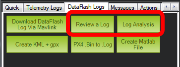
在左下角,选择“数据闪存日志”项,并点击“通过Mavlink下载数据日志”按钮。

然后,选择要下载的日志。这些日志保存到你的MissionPlanner/logs目录中,该文件夹以飞行器类型命名,例如QUADCOPTER。
自动分析日志
Mission Planner:开始日志分析
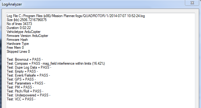
最简单的分析是自动生成一个基本的报告,该报告将突出显示常见问题区域。点击“日志分析”,并选择一个你已经保存到MissionPlanner/logs目录的日志。
它们将被放在以飞行器类型命名的文件夹中,比如QUADCOPTER或ROVER。
一旦你选择了你想要的日志,它将生成一个像这样的报告:
手工回顾日志
要获得更详细的分析,点击“回顾日志”,并选择一个你已经保存到MissionPlanner/logs目录下的日志。同样,它们将被放在以飞行器类型命名的文件夹中,比如QUADCOPTER或ROVER。
从互联网或飞控下载的日志进行回顾的步骤
闪存日志的文件名后缀是 .bin 或者 .log 。
下载日志文件。请注意它一般会下载到你电脑中的下载目录。
打开Mission Planner。
打开“飞行数据”页面(左上角)。
选择“数据闪存日志”项。
点击“回顾日志”按钮。
一个标准的Windows“打开文件”对话框会让你选择下载好的.bin文件。
读取日志之后,将打开一个Manual log Review窗口,它允许你从日志中绘制数据以供查看。(见下文)
查看日志数据
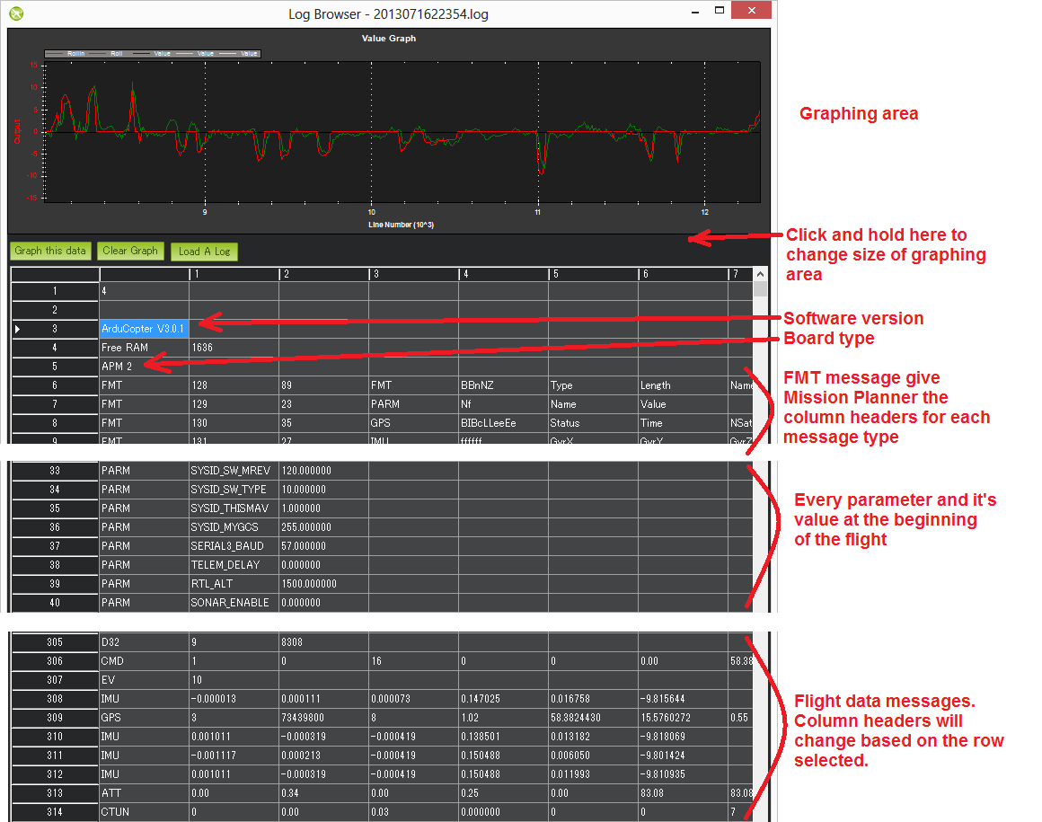
一旦选择了你想要的日志,将得到如下所示的图表。闪存日志的基本格式为:
行号出现在查看器的最左边。
软件版本和飞快型号显示在顶部。
接下来是FMT消息,它告诉Mission Planner每种消息类型的列标题。
PARM行显示每个参数(按在eeprom中出现的顺序)及其在飞行开始时的值。
飞行数据信息,包括GPS、IMU等。
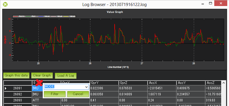
首先单击所需要的行,以图形化方式显示飞行数据,你应该会看到列标题会同步更新。接下来找到你要绘制图形的列,单击它,然后按“绘制此数据”按钮。在上面的示例中,已绘制了ATT的Roll-In和Roll数据。鼠标的滚轮可用于放大或缩小。你也可以选择图表的一个区域以放大它。通过单击鼠标右键并选择“将比例设置为默认值”来缩小。这是有关使用此功能的简单教程。你也可以通过单击第一列并从下拉列表中选择消息类型,只对第一列(飞行数据消息类型)进行筛选。这是非常有用的,特别是查看不同的飞行模式(称为“模式”信息)期间使用的任务。再次单击第一列,然后按“取消”以清除过滤器。
设置要记录的数据
在数据闪存中记录哪些消息由LOG_BITMASK参数控制。
消息详细信息(限于直升机)
注意:许多消息在每类飞行器的Wiki部分的“板载信息日志消息”页面中进行了详细说明。
| DesRoll | The pilot’s desired roll angle in degrees (roll left is negative, right is positive) |
| Roll | The vehicle’s actual roll in degrees (roll left is negative, right is positive) |
| DesPitch | The pilot’s desired pitch angle in degrees (pitch forward is negative, pitch back is positive) |
| Pitch | The vehicle’s actual pitch angle in degrees (pitch forward is negative, pitch back is positive) |
| DesYaw | The pilot’s desired heading in degrees with 0 = north |
| Yaw | The vehicle’s actual heading in degrees with 0 = north |
| ErrRP | The average size of the roll/pitch error estimate (values between 0 and 1) |
| ErrYaw | The average size of the yaw error estimate (values between 0 and 1) |
ATUN (auto tune overview):
| Axis: 0 = Roll, 1 = Pitch | |
| TuneStep | 0 = Returning towards Level (before or after a test), 1 = Testing (i.e. performing a twitch to test response), 2 = Updating gains (twitch completed and gains adjusted) |
| RateMin | Minimum recorded rate during this test |
| RateMax | Maximum recorded rate during this test |
| RPGain | Rate P gain value being tested |
| RDGain | Rate D gain value being tested |
| SPGain | Stabilize P gain being tested |
ATDE (auto tune step details):
| Angle | Angle of the copter in centi-degrees for the axis being testedx |
| Rate | Rate of rotation of the copter for the axis being tested |
CAM (time and position when camera shutter was activated):
| GPSTime | The GPS reported time since epoch in milliseconds |
| Lat | The accelerometer + GPS latitude estimate |
| Lng | The accelerometer + GPS longitude estimate |
| Alt | The accelerometer + barometer estimated altitude in cm above ground |
| Roll | The vehicle roll angle in centi-degrees |
| Pitch | The vehicle pitch angle in centi-degrees |
| Yaw | The vehicle’s heading in centi-degrees |
CMD (commands received from the ground station or executed as part of a mission):
| CTot | The total number of commands in the mission |
| CNum | This command’s number in the mission (0 is always home, 1 is the first command, etc) |
| CId | The MAVLink message id |
| Copt | The option parameter (used for many different purposes) |
| Prm1 | The command’s parameter (used for many different purposes) |
| Alt | The command’s altitude in meters |
| Lat | The command’s latitude position |
| Lng | The command’s longitude position |
COMPASS (raw compass, offset and compassmot compensation values):
| Field | Description |
| MagX, MagY. MagZ | Raw magnetic field values for x, y and z axis |
| OfsX, OfsY, OfsZ | Raw magnetic offsets (will only change if COMPASS_LEARN parameter is 1) |
| MOfsX, MOfsY, MOfsZ | Compassmot compensation for throttle or current |
CURRENT (battery voltage, current and board voltage information):
| FIELD | DESCRIPTION |
| Thr | Pilot input throttle from 0 ~ 1000 |
| ThrInt | Integrated throttle (i.e. sum of total throttle output for this flight) |
| Volt | Battery voltage in volts * 100 |
| Curr | Current drawn from the battery in amps * 100 |
| Vcc | Board voltage |
| CurrTot | Total current drawn from battery |
CTUN (Control, Throttle and altitude information):
| FIELD | DESCRIPTION |
| TimeUS | Time stamp for messages in microseconds (can be ignored) |
| ThI | The pilot’s throttle in as a number from 0 to 1000 |
| ABst | Angle Boost: throttle increase (from 0 ~ 1000) as a result of the copter leaning over (automatically added to all pilot and autopilot throttle to reduce altitude loss while leaning) |
| ThO | Final throttle output sent to the motors (from 0 ~ 1000). Normally equal to ThrI+ABst while in stabilize mode. |
| ThH | Estimated throttle required to hover throttle in the range 0 ~ 1 |
| DAlt | The Desired Altitude while in AltHold, Loiter, RTL or Auto flight modes. It is influenced by EKF origin, which in 3.5.X is corrected by GPS altitude. This behaviour is turned off in 3.6.X and can be turned on with EKF_OGN_HGT_MASK. |
| Alt | The current EKF Altitude |
| BAlt | Barometer Altitude: The altitude above ground according to the barometer |
| DSAlt | Desired distance in cm from ground or ceiling (only visible if Sonar is available) |
| SAlt | Sonar Altitude: the altitude above ground according to the sonar (Only visible of Sonar is available) |
| TAlt | Terrain altitude (not used by default) |
| DCRt | Desired Climb Rate in cm/s |
| CRt | Climb Rate in cm/s |
| N | Harmonic notch current center frequency for gyro in Hz |
D32, DU32 (single data values which are either signed 32bit integers or unsigned 32bit integers):
| FIELD | DESCRIPTION |
| id | Identification number for the variable. There are only two possible values:
|
EKF (Extended Kalman Filter):
Log information here(Dev Wiki). Overview here.
ERR (an error message):
SubSystem and Error codes listed below
| Subsys | ECode and Description |
|---|---|
| 2 = Radio |
|
| 3 = Compass |
|
| 5 = Radio Failsafe |
|
| 6 = Battery Failsafe |
|
| 8 = GCS Failsafe |
|
| 9 = Fence Failsafe |
|
| 10 = Flight mode Change failure | Vehicle was unable to enter the desired flight mode normally because of a bad position estimate |
| 11 = GPS |
|
| 12 = Crash Check |
|
| 13 = Flip mode | 2 = Flip abandoned (not armed, pilot input or timeout) |
| 15 = Parachute |
|
| 16 = EKF Check |
|
| 17 = EKF Failsafe |
|
| 18 = Barometer |
|
| 19 = CPU Load Watchdog |
|
| 20 = ADSB Failsafe |
|
| 21 = Terrain Data | 2 = missing terrain data |
| 22 = Navigation |
|
| 23 = Terrain Failsafe |
|
| 24 = EKF Primary changed |
|
| 25 = Thrust Loss Check |
|
| 26 = Sensor Failsafe (Sub) |
|
| 27 = Leak Failsafe (Sub) |
|
| 28 = Pilot Input Timeout Failsafe (Sub only) |
|
| 29 = Vibration Failsafe |
|
EV: (an event number). The full list of possible events can be found in AP_Logger.hbut the most common are:
| Event No | DESCRIPTION |
| 10 | Armed |
| 11 | Disarmed |
| 15 | Auto Armed (pilot has raised throttle above zero and autopilot is free to take control of throttle) |
| 18 | Land Complete |
| 25 | Set Home (home location coordinates have been capture) |
| 28 | Not Landed (aka Takeoff complete) |
GPA: (Global Position Accuracy)
| FIELD | DESCRIPTION |
| VDop | Vertical dilution of precision, a unitless measure of precisionhttps://en.wikipedia.org/wiki/Dilution_of_precision |
| HAcc | Horizontal Accuracy as reported by the GPS module, in meters |
| VAcc | Vertical Accuracy as reported by the GPS module, in meters |
| SAcc | Speed accuracy as reported by the GPS, in m/s/s |
| VV |
|
| SMS | The autopilot time in milliseconds that the accuracy/GPS position data is associated with. |
| Delta | The time between when the previous GPS message and the current GPS message was parsed by the autopilot, in milliseconds |
GPS:
| FIELD | DESCRIPTION |
| Status | 0 = no GPS, 1 = GPS but no fix, 2 = GPS with 2D fix, 3 = GPS with 3D fix |
| Time | The GPS reported time since epoch in milliseconds |
| NSats | The number of satellites current being used |
| HDop | A measure of gps precision (1.5 is good, >2.0 is not so good)https://en.wikipedia.org/wiki/Dilution_of_precision |
| Lat | Lattitude according to the GPS |
| Lng | Longitude according to the GPS |
| RelAlt | Accelerometer + Baro altitude in meters |
| Alt | GPS reported altitude (not used by the autopilot) |
| SPD | Horizontal ground speed in m/s |
| GCrs | Ground course in degrees (0 = north) |
IMU (accelerometer and gyro information):
| FIELD | DESCRIPTION |
| GyrX, GyrY, GyrZ | The raw gyro rotation rates in radians/second |
| AccX, AccY, AccZ | The raw accelerometer values in m/s/s |
Mode (flight mode):
| FIELD | DESCRIPTION |
| Mode | The flight mode displayed as a string (i.e. STABILIZE, LOITER, etc) |
| ThrCrs | Throttle cruise (from 0 ~ 1000) which is the autopilot’s best guess as to what throttle is required to maintain a stable hover |
| Rsn | Reason for mode change (TX command, failsafe, etc) . The meaning of code values can be found in your vehicle’s define.h file (under the mode_reason_t enum). For instance for ArduCopter the file is Arducopter/define.h |
NTUN (navigation information):
| FIELD | DESCRIPTION |
| WPDst | Distance to the next waypoint (or loiter target) in cm. Only updated while in Loiter, RTL, Auto. |
| WPBrg | Bearing to the next waypoint in degrees |
| PErX | Distance to intermediate target between copter and the next waypoint in the latitude direction |
| PErY | Distance to intermediate target between copter and the next waypoint in the longitude direction |
| DVelX | Desired velocity in cm/s in the latitude direction |
| DVelY | Desired velocity in cm/s in the longitude direction |
| VelX | Actual accelerometer + gps velocity estimate in the latitude direction |
| VelY | Actual accelerometer + gps velocity estimate in the longitude direction |
| DAcX | Desired acceleration in cm/s/s in the latitude direction |
| DAcY | Desired acceleration in cm/s/s in the longitude direction |
| DRol | Desired roll angle in centi-degrees |
| DPit | Desired pitch angle in centi-degrees |
PM (performance monitoring):
| FIELD | DESCRIPTION |
| NLon | Number of long running main loops (i.e. loops that take more than 20% longer than they should according to SCHED_LOOP_RATE - ex. 3ms for 400Hz rate) |
| NLoop | The total number of loops since the last PM message was displayed. This allows you to calculate the percentage of slow running loops (which should never be higher than 15%). Note that the value will depend on the autopilot clock speed |
| MaxT | The maximum time that any loop took since the last PM message. This shouldn’t exceed 120% of scheduler loop period, but will be much higher during the interval where the motors are armed |
| Mem | Available memory, in bytes |
| Load | Percentage (times 10) of the scheduler loop period when CPU is used |